At IWM, our fine wire is drawn to meet our customers’ exacting specification ensuring best value to our customers’ manufacturing processes and product quality. IWM is in continuous production of single end, round wire drawn from aluminum, copper alloys, and low carbon steel coil and rod materials. More details concerning material specifications can be found in our materials technical guide. Below, please find specifications concerning our wire sizes, processes, metal treatments, and packaging solutions for your design considerations.
Wire Sizes
IWM offers fine wire in diameters starting at 0.005in. (36ga.) as well as larger diameters produced through our intermediate process dies. Below is listed the American Wire Gauge (AWG) standard reference size chart and size ranges for IWM intermediate and fine wire. For a current list of wire sizes, please contact IWM at solutions@iwmesh.com.
| AWG | Inches | Millimeters |
|---|---|---|
| 17 | 0.0453 | 1.150 |
| 18 | 0.0403 | 1.024 |
| 19 | 0.0359 | 0.912 |
| 20 | 0.0320 | 0.812 |
| 21 | 0.0285 | 0.723 |
| 22 | 0.0253 | 0.644 |
| 23 | 0.0226 | 0.573 |
| 24 | 0.0201 | 0.511 |
| 25 | 0.0179 | 0.455 |
| 26 | 0.0159 | 0.405 |
| 27 | 0.0142 | 0.361 |
| 28 | 0.0126 | 0.321 |
| 29 | 0.0113 | 0.286 |
| 30 | 0.0100 | 0.255 |
| 31 | 0.00893 | 0.227 |
| 32 | 0.00795 | 0.202 |
| 33 | 0.00708 | 0.180 |
| 34 | 0.00630 | 0.160 |
| 35 | 0.00561 | 0.143 |
| 36 | 0.00500 | 0.127 |
| 0000 (4/0) | 0.4600 | 11.684 |
| 000 (3/0) | 0.4096 | 10.405 |
| 00 (2/0) | 0.3648 | 9.266 |
| 0 (1/0) | 0.3249 | 8.251 |
| 1 | 0.2893 | 7.348 |
| 2 | 0.2576 | 6.544 |
| 3 | 0.2294 | 0.2294 |
| 4 | 0.2043 | 5.189 |
| 5 | 0.1819 | 4.621 |
| 6 | 0.1620 | 4.115 |
| 7 | 0.1443 | 3.665 |
| 8 | 0.1285 | 3.264 |
| 9 | 0.1144 | 2.906 |
| 10 | 0.1019 | 2.588 |
| 11 | 0.0907 | 2.305 |
| 12 | 0.0808 | 2.053 |
| 13 | 0.0720 | 1.828 |
| 14 | 0.0641 | 1.628 |
| 15 | 0.0571 | 1.450 |
| 16 | 0.0508 | 1.291 |
| 37 | 0.00445 | 0.113 |
| 38 | 0.00397 | 0.101 |
| 39 | 0.00353 | 0.0897 |
| 40 | 0.00314 | 0.0799 |
Fine Wire Processes
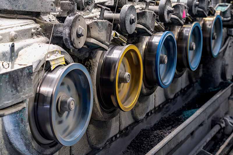
Wire Drawing is a progressive process which the metal is stretched and formed from a larger diameter to smaller diameters through a successive series of precision dies and drawing wheels (capstans) which pull the wire. At IWM, our wire is drawn to an intermediate size, which may be then conditioned prior to drawing to its final fine wire dimension.

Intermediate Size Wire Processing
Fine Wire Metal Treatments & Coatings
As the wire is drawn, the material is strain-hardened and the material loses its ductility. Thus, prior to final wire drawing, the intermediate wire is soft-annealed to improve the wire’s ductility to minimize breaks during the final wire drawing processes.
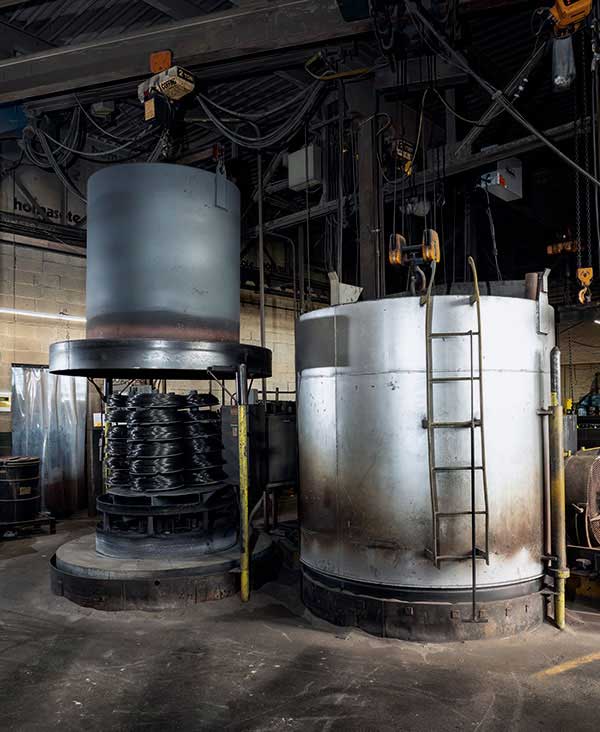
Annealing is the heat treatment process for increasing the metal’s ductility and reducing its hardness. At IWM, both annealing ovens and furnaces are utilized to stabilize, partially anneal, and fully (soft) anneal our wire. The annealing process requires precision control of temperature (heat & cooling), time, and atmosphere to ensure the desired mechanical properties of the wire. IWM process quality control and monitoring ensures consistent annealing processes to eliminate issues found during the annealing process such as microstructural inclusions, decarburization, and carbon sooting.
Tempering is the heat treatment process to increase the metal’s hardness, which is performed by heating the metal just below its recrystallization value and sustaining it at that temperature for a duration of time. For harder materials, this relieves internal stresses providing improved ductility. This process is common for wire springs and other tensioned products.
Galvanizing is the process of applying zinc to a ferrous metal to inhibit surface corrosion. For wire, this is performed either via Hot Dipped Galvanizing (HDG) or via Electroplating. The HDG processing of wire can be performed via a batch process (vat dipped) or via a continuous process. For both the batch or continuous processes the wire is cleaned, then processed to remove any surface oxidation (pickling, fluxing), and then submerged into heated molten zinc where through a diffusion process the zinc reacts with the iron to form a protective coating of the wire. The coating thickness of wire through the HDG process can be as much as 300g/m². Galvanizing through electroplating is performed through electro-deposition process where the wire, which acts as a cathode, attracts the zinc (anode) which is ionized through a zinc sulfate solution. Electro-plating can deposit as much as 915g/m² and can be drawn or reduced up to 95% of its origin area while maintaining adequate coating for surface corrosion for intermediate and fine wire size diameters.
Copper Coating
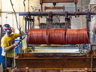
IWM typically copper coats its low carbon steel wire where the copper acts as both a surface lubricant for the fine wire drawing process as well as a corrosion inhibitor and/or conductor for the fine wire’s use or application. Copper coating can be applied through a chemical coating (immersion coating) of the wire through an acidic copper solution after the wire has been properly cleaned and surface treated (pickled).

Bell Annealing Ovens

Batch Copper Coating
Fine Wire Packing Solutions
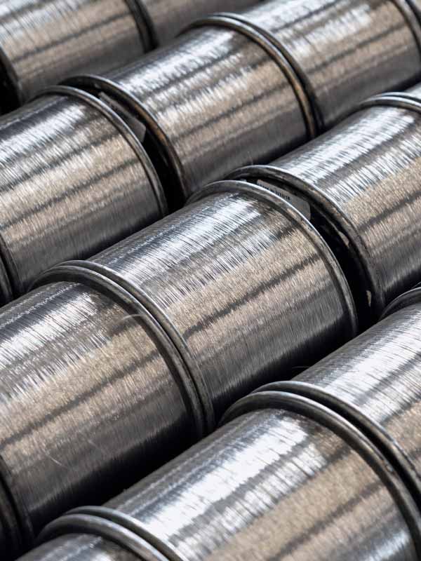
IWM’s packaging solutions for fine wire are customized to meet our customers’ payoff requirements, while ensuring best value when considering logistics and handling. Typical packaging consideration can include, but are not limited to wire lay & lay direction; size & weight of spool, reel, or stem; spool material types; quality considerations such as foreign object debris (FOD) control and electro-static discharge (ESD) preventive packaging; bulk pallet or rack sizes; and returnable rack and equipment programs for continuous or KANBAN programs.
For more details concerning packaging options, please contact IWM at solutions@iwmesh.com. For general spool packaging consideration, please find IWM’s standard spool sizes.

| IWM P/N | Material | Flange O.D. (inches) | Traverse (inches) | Hub Diameter (inches) | Bore Diameter (inches) |
|---|---|---|---|---|---|
| 7460 | Steel | 8.0 | 5.75 | 3.35 | 3.0 |
| 7461 | Steel | 8.0 | 9.0 | 3.35 | 3.0 |
| 7465 | Steel | 10.8 | 11.5 | 6.0 | 3.0 |
| 7471 | Wood/Steel | 30.0 | 11.0 | 16.0 | 5.0 |
| 7472 | ABS | 8.000 | 6.000 | 4.500 | 3.000 |
| 7481 | Plastic | 2.500 | 2.750 | 1.500 | 0.625 |
| 7482 | Plastic | 2.500 | 4.125 | 1.500 | 0.625 |
| 7484 | Steel | 30.00 | 11.00 | 16.00 | 5.000 |
| 7486 | Steel | 8.500 | 6.000 | 5.000 | 4.500 |
| 7487 | Steel | 8.500 | 6.000 | 5.000 | 4.500 |
| 7493 | Steel | 10.00 | 6.000 | 4.500 | 1.250 |
| 7494 | Aluminum | 8.000 | 6.000 | 4.000 | 3.500 |
| 7495 | Steel | 8.000 | 6.000 | 4.500 | 3.000 |
| 7498 | Steel | 10.00 | 6.000 | 4.500 | 1.250 |
| 7499 | Steel | 8.000 | 6.000 | 4.500 | 1.250 |
| 7500 | Fiber | 7.750 | 6.250 | 3.875 | 3.500 |
| 7501 | Steel | 8.000 | 6.000 | 4.500 | 1.250 |
| 7502 | Steel | 8.000 | 6.000 | 4.500 | 3.000 |
| 7507 | Aluminum | 8.000 | 6.000 | 4.500 | 1.250 |
| 7509 | Steel | 8.000 | 6.000 | 4.500 | 3.000 |
| 7510 | Steel | 8.500 | 6.000 | 4.500 | 3.500 |
| 7513 | Steel | 8.000 | 6.000 | 4.500 | 3.500 |
| 7600 | Steel | 11.375 | 11.00 | 8.250 | 6.250 |

| IWM P/N | Material | Flange O.D. (inches) |
Traverse (inches) |
|---|---|---|---|
| 7460 | Steel | 8.0 | 5.75 |
| Hub Diameter (inches) |
Bore Diameter (inches) |
||
| 3.35 | 3.0 | ||
| IWM P/N | Material | Flange O.D. (inches) |
Traverse (inches) |
| 7461 | Steel | 8.0 | 9.0 |
| Hub Diameter (inches) |
Bore Diameter (inches) |
||
| 3.35 | 3.0 | ||
| IWM P/N | Material | Flange O.D. (inches) |
Traverse (inches) |
| 7465 | Steel | 10.8 | 11.5 |
| Hub Diameter (inches) |
Bore Diameter (inches) |
||
| 6.0 | 3.0 | ||
| IWM P/N | Material | Flange O.D. (inches) |
Traverse (inches) |
| 7471 | Wood/Steel | 30.0 | 11.0 |
| Hub Diameter (inches) |
Bore Diameter (inches) |
||
| 16.0 | 5.0 | ||
| IWM P/N | Material | Flange O.D. (inches) |
Traverse (inches) |
| 7472 | ABS | 8.000 | 6.000 |
| Hub Diameter (inches) |
Bore Diameter (inches) |
||
| 4.500 | 3.000 | ||
| IWM P/N | Material | Flange O.D. (inches) |
Traverse (inches) |
| 7481 | Plastic | 2.500 | 2.750 |
| Hub Diameter (inches) |
Bore Diameter (inches) |
||
| 1.500 | 0.625 | ||
| IWM P/N | Material | Flange O.D. (inches) |
Traverse (inches) |
| 7482 | Plastic | 2.500 | 4.125 |
| Hub Diameter (inches) |
Bore Diameter (inches) |
||
| 1.500 | 0.625 | ||
| IWM P/N | Material | Flange O.D. (inches) |
Traverse (inches) |
| 7484 | Steel | 30.00 | 11.00 |
| Hub Diameter (inches) |
Bore Diameter (inches) |
||
| 16.00 | 5.000 | ||
| IWM P/N | Material | Flange O.D. (inches) |
Traverse (inches) |
| 7486 | Steel | 8.500 | 6.000 |
| Hub Diameter (inches) |
Bore Diameter (inches) |
||
| 5.000 | 4.500 | ||
| IWM P/N | Material | Flange O.D. (inches) |
Traverse (inches) |
| 7487 | Steel | 8.500 | 6.000 |
| Hub Diameter (inches) |
Bore Diameter (inches) |
||
| 5.000 | 4.500 | ||
| IWM P/N | Material | Flange O.D. (inches) |
Traverse (inches) |
| 7493 | Steel | 10.00 | 6.000 |
| Hub Diameter (inches) |
Bore Diameter (inches) |
||
| 4.500 | 1.250 | ||
| IWM P/N | Material | Flange O.D. (inches) |
Traverse (inches) |
| 7494 | Aluminum | 8.000 | 6.000 |
| Hub Diameter (inches) |
Bore Diameter (inches) |
||
| 4.000 | 3.500 | ||
| IWM P/N | Material | Flange O.D. (inches) |
Traverse (inches) |
| 7495 | Steel | 8.000 | 6.000 |
| Hub Diameter (inches) |
Bore Diameter (inches) |
||
| 4.500 | 3.000 | ||
| IWM P/N | Material | Flange O.D. (inches) |
Traverse (inches) |
| 7498 | Steel | 10.00 | 6.000 |
| Hub Diameter (inches) |
Bore Diameter (inches) |
||
| 4.500 | 1.250 | ||
| IWM P/N | Material | Flange O.D. (inches) |
Traverse (inches) |
| 7499 | Steel | 8.000 | 6.000 |
| Hub Diameter (inches) |
Bore Diameter (inches) |
||
| 4.500 | 1.250 | ||
| IWM P/N | Material | Flange O.D. (inches) |
Traverse (inches) |
| 7500 | Fiber | 7.750 | 6.250 |
| Hub Diameter (inches) |
Bore Diameter (inches) |
||
| 3.875 | 3.500 | ||
| IWM P/N | Material | Flange O.D. (inches) |
Traverse (inches) |
| 7501 | Steel | 8.000 | 6.000 |
| Hub Diameter (inches) |
Bore Diameter (inches) |
||
| 4.500 | 1.250 | ||
| IWM P/N | Material | Flange O.D. (inches) |
Traverse (inches) |
| 7502 | Steel | 8.000 | 6.000 |
| Hub Diameter (inches) |
Bore Diameter (inches) |
||
| 4.500 | 3.000 | ||
| IWM P/N | Material | Flange O.D. (inches) |
Traverse (inches) |
| 7507 | Aluminum | 8.000 | 6.000 |
| Hub Diameter (inches) |
Bore Diameter (inches) |
||
| 4.500 | 1.250 | ||
| IWM P/N | Material | Flange O.D. (inches) |
Traverse (inches) |
| 7509 | Steel | 8.000 | 6.000 |
| Hub Diameter (inches) |
Bore Diameter (inches) |
||
| 4.500 | 3.000 | ||
| IWM P/N | Material | Flange O.D. (inches) |
Traverse (inches) |
| 7510 | Steel | 8.500 | 6.000 |
| Hub Diameter (inches) |
Bore Diameter (inches) |
||
| 4.500 | 3.500 | ||
| IWM P/N | Material | Flange O.D. (inches) |
Traverse (inches) |
| 7513 | Steel | 8.000 | 6.000 |
| Hub Diameter (inches) |
Bore Diameter (inches) |
||
| 4.500 | 3.500 | ||
| IWM P/N | Material | Flange O.D. (inches) |
Traverse (inches) |
| 7600 | Steel | 11.375 | 11.00 |
| Hub Diameter (inches) |
Bore Diameter (inches) |
||
| 8.250 | 6.250 | ||


